

Pneumatic two-seat control valve
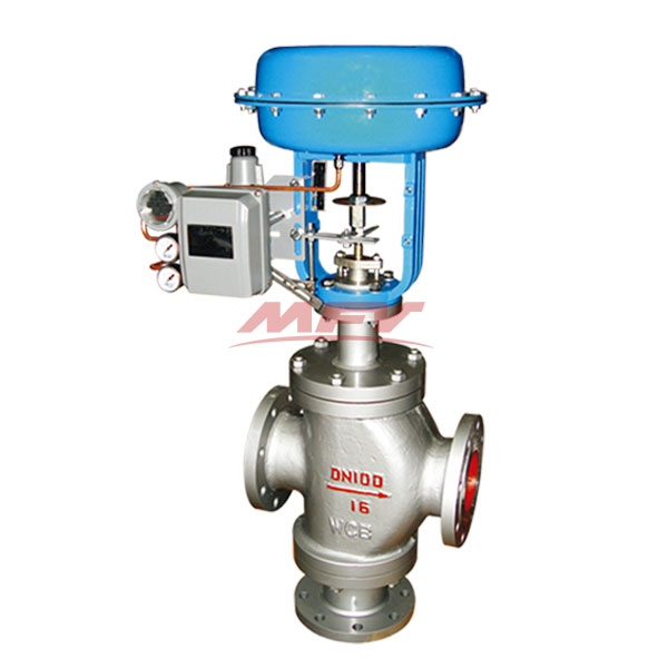
Pneumatic two-seat control valve
Nominal diameter: DN25 ~ 400mm
Nominal pressure: PN16 ~ 64MPa
Temperature: -250 ℃ ~ + 560 ℃
Main material: HT200, ZG230-450, ZG1Cr18Ni9Ti, ZG0Cr18Ni12Mo2Ti
Medium gas, liquid, vapor, etc.: Medium
Drive mode: pneumatic
Design criteria: GB / T17213
Flange standard: GB / T9113, JB / T79 , HG20594 and other standard
Inspection standards: GB / T4213
Form connect: flange (FF RF RTJ), welding (SW BW), thread ( Suitable for 1 "or less
First, the pneumatic two-seat control valve overview
ZJHN pneumatic two-seat control valve with double-guided structure, equipped with multi-spring recruit agencies. Has the advantages of compact structure, light weight, action sensitive, large valve capacity, accurate flow characteristics, easy disassembly. Pneumatic two-seat control valve is widely used in precise control of gas, liquid, steam and other media process parameters such as pressure, flow, temperature, liquid level at a given value. Particularly suitable for large pressure drop, allowing greater leakage and not very clean media occasions.
Pneumatic two-seat control valve products are standard, bellows sealed, jacket insulation and other varieties. Product nominal pressure rating PN16, 40, 64; body diameter range DN25 ~ 400. Applicable fluid temperature -250 ℃ ~ + 560 ℃ range of a variety of grades. Leakage standards for grade Ⅲ and Ⅳ. Flow characteristics are linear or percentage. A wide variety of specifications to choose from.
Second, pneumatic two-seat control valve main parts and materials
Part Name | material | temperature range |
Body valve cover | HT200 | -20 ~ 200 ℃ |
ZG230-450 | -40 ~ 450 ℃ | |
ZG1Cr18Ni9Ti | -250 ~ 550 ℃ | |
ZG0Cr18Ni12Mo2Ti | -250 ~ 550 ℃ | |
Spool, seat | 1Cr18Ni9 | -250 ~ 550 ℃ |
0Cr18Ni12Mo2Ti | -250 ~ 550 ℃ | |
filler | Teflon | -40 ~ 200 ℃ |
Diaphragm | NBR rubber reinforced polyester fabrics | |
compressed spring | 60Si2Mn | |
Membrane cover | A3 |
Third, pneumatic two-seat control valve main technical parameters
Nominal diameter mm | 25 | 32 | 40 | 50 | 65 | 80 | 100 | 125 | 150 | 200 | 250 | 300 | 400 | ||
Rated flow coefficient kv | 10 | 16 | 25 | 40 | 63 | 100 | 250 | 250 | 400 | 630 | 100 | 1600 | 2700 | ||
Nominal pressure MPa | 1.6 4.0 6.4 | ||||||||||||||
Travel mm | 16 | 25 | 40 | 63 | 100 | ||||||||||
Medium temperature ℃ | -40 ~ 230 ℃ (room temperature type), heat sink 230 ~ 450 ℃ (medium temperature), special order -100 ~ 600 ℃ | ||||||||||||||
Flow characteristics | Straight line, equal percentage | ||||||||||||||
Flange standard | In line with JB78-59, JB79-59 standards, according to JB / 79.1-94, JB / 79.2-94, ANSI, JIS, DIN and other standard production orders | ||||||||||||||
Body material | PN (MPa) | 1.6 | WCB (ZG230-450) CF3CF8 CF8M | ||||||||||||
4.0,6.0 | WCB (ZG230-450), ZG1Cr18Ni9Ti, ZG0Cr18Ni12Mo2Ti CF8 CF8M | ||||||||||||||
Spool material | 1Cr18Ni9,0Cr18Ni12Mo2Ti CF8 CF8M | ||||||||||||||
On the bonnet type | Ordinary type (normal temperature type), hot type (medium temperature type) | ||||||||||||||
Adjustable ratio | 30: 1 | ||||||||||||||
Air source connector | M16 × 1.5 | ||||||||||||||
Fourth, pneumatic two-seat control valve pneumatic actuator
model | ZHA (B) -1 | ZHA (B) -2 | ZHA (B) -3 | ZHA (B) -4 | ZHA (B) -5 | ZHA (B) -6 |
Effective area of cm2 | 200 | 280 | 400 | 630 | 1000 | 1600 |
Travel mm | 10 | 16 | 25 | 40 | 60 | 1000 |
Spring range KPa | 20 to 100 (standard); 20 to 100, 40 to 200, 20 to 60, 60 to 100, 80 to 240 | |||||
Fifth, pneumatic two-seat control valve pneumatic actuator main technical performance indicators
project | Index value | |
Basic error% | Without locator | ± 5.0 |
With locator | ± 1.0 | |
Backlash% | Without locator | 3.0 |
With locator | 1.0 | |
dead zone% | Without locator | 3.0 |
With locator | 0.4 | |
Permissible leakage L / h | 1 × 10⁻³ × valve rated capacity | |
Sixth, pneumatic two-seat control valve actuator allows pressure
Supply pressure MPa | Spring pressure KPa | Nominal diameter | |||||||||||
25 | 32 | 40 | 50 | 65 | 80 | 100 | 125 | 150 | 200 | 250 | 300 | ||
0.14 | 20-100 | 5.4 | 4.4 | 4.9 | 3.8 | 4.7 | 3.6 | 2.8 | 3.75 | 2.7 | 2.15 | 2.0 | 1.7 |
0.24 | 40-200 | 10.8 | 8.8 | 9.8 | 7.6 | 9.4 | 7.2 | 5.6 | 7.5 | 5.4 | 4.3 | 4.0 | 3.4 |
Note: The condition of use is P2 = 0 when the stem is out of the media outlet.
Seven, pneumatic two-seat control valve dimensions
Public Path (mm) | 25 | 32 | 40 | 50 | 65 | 80 | 100 | 125 | 150 | 200 | 250 | 300 | |
L (mm) | PN1.6MPa | 185 | 200 | 220 | 250 | 275 | 300 | 350 | 410 | 450 | 550 | 670 | 770 |
PN4.0MPa | 190 | 210 | 230 | 255 | 285 | 310 | 335 | 425 | 460 | 560 | 740 | 805 | |
PN6.4MPa | 200 | 210 | 235 | 265 | 295 | 320 | 370 | 440 | 475 | 570 | 750 | 820 | |
H (mm) | normal type | 567 | 570 | 645 | 650 | 877 | 887 | 899 | 1058 | 1068 | 1110 | 1498 | 1574 |
Heat sink type | 697 | 700 | 775 | 780 | 1040 | 1050 | 1062 | 1257 | 1267 | 1309 | 1743 | 1819 | |
H1 (mm) | 117 | 120 | 139 | 144 | 188 | 208 | 220 | 268 | 278 | 320 | 441 | 503 | |
D (mm) | 225 | 360 | 470 | 620 | |||||||||
Weight (KG) | 33 | 35 | 47 | 51 | 98 | 111 | 148 | 236 | 292 | 433 | 760 | 920 | |
 |  Shandong Hugong Valve Manufacturing Co., Ltd.  91, Zhongnan High-tech Yuandu Huizhi Industrial Park, Taixiang Street and Wenhua Road, Weifang Economic Development Zone, Shandong +86-15963678999 sdhgfm@163.com |  |
Copyright ? Shandong Hugong Valve Manufacturing Co., Ltd.
Record number: No. 18000630-1 Lu ICP


